Professional architectural drawings is an article that defines its 3 key stages. The essential steps of preparing them by an architect and seniors. Also, it’s importance for architectural practice daily work.
Table of Contents
Background – professional architectural drawings
2-Non – architectural elements
1-Drawings data linked with other disciplines
2-Drawing data linked with project specs
Architects and seniors prepare professional architectural drawings as part of the architectural design process. In addition to its importance in daily practice, it shows a practice innovation and work excellence. Many professional bodies, for example, RIBA, AIA, and others in Europe, focus on this matter. They published documents but merely talked about or interviewing firm seniors to show the boundaries of this aspect. That is without focusing on content, which is more important.
To date, they have not published any useful information on the key stages of preparing professional architectural drawings.
The publications talk about general management and personal qualities of individuals working in the field. Many ask why then they disallow people from practicing, but only after qualifying them.
What do these bodies qualify people in terms of technical skills, knowledge, and experience? What is their contribution to architects and practice in terms of development?
Accuracy of professional architectural drawings
Architects and seniors tend to check and review drawings occasionally to check compliance with the internal firm system. This review stands for raising quality, reducing work time, and lowering the firm’s work cost. Here I start from the first early step, starting a drawing.
I have witnessed in my previous years of experience that Architects and seniors start drawing with a click. This on a point in the model space (AutoCAD) without focusing on the importance of the origin x, y, z, (0,0,0). Drawing on any location in the coordinates of the model space has many effects on the ongoing and future drawing preparations.
For example, if an architect starts a drawing at any point on the model space using a scale of 1:1, he will face a problem. In this scale, the drawing is very small. And in addition, when he (zooms all), which is very common in preparing drawings, the screen jumps to The Origin x, y, z. Thus, the architect will face a hurdle when drawing to bring what he is drawing into the middle of the screen.
Though this will not take much time, it creates frustration and loss of focus. Therefore, that becomes a major need to control professional architectural drawing preparations.
Architects and seniors, when preparing drawings, must think of the drawing units set up. Also, units and drawings, and their relation to the drawing layout. In this way, you can scale and link a drawing to a layout easily. When he sets up the layout to the printing sheet, let’s say A1 or A0, he can control all the entire drawing process easily. That is to avoid waste of time and not to lose focus.
For example, when the architect starts the drawing in the origin x, y, z (0,0,0) and has the boundary of 20 meters by 50 meters, and in centimeters that’s 2,000 by 5,000, which is relatively medium sized in drawing. Also, when you prepare for plotting, you go for zoom all to plot in the correct scale. This will bring the drawing to the front of the paper space layout, which you can see clearly.
And when the architect set up the printing scale, after that, the drawing jumps into the front of the layout.
While when the architect starts drawing in the model space and wants to print, he does the following. He gives command Zoom all we’re here, he loses the drawing because the screen will come to the origin. In this way, it will be a hurdle to control the rest of the printing.
Many architects I have worked with in my career fill drawings with layers. See Figure 1, my colleague’s working drawings for a multi-story building in the Middle East. That is correct to control the drawing elements. But here he has to create a CTB file that includes all 255 colors and their line weight. In addition, he must do this for all files of the project. Meanwhile, the architect can use the 9 main AutoCAD colors for the drawing. This will reduce the time for creating a CTB file for every file.

In addition, the property palette he needs to control line properties and scale.
To make using layers max accurate the architect can show the priority of drawing elements’ importance. For example, walls are first to have a color (from the 9). The openings are also the same way. Elements above the cut line have a color. Elements below the cut line one color as well. In this way, the layout palette will be easy to use because you only assign a color to the layer.
In the plot dialog box, you will assign a line weight for the 9 colors before you give the command to print. This makes the drawing very accurate, less time-consuming, and easy to manage and to prepare.
The second key stage represents how an architect or a senior shows the drawing data and information. While professional architectural drawings represent drafting, but in addition is design and planning. The drawings that architects prepare include the architectural elements and non-elements.
It’s all the elements of a project, the structural and non-structural. These include walls, openings, doors, windows, and ceilings. In addition to slabs, floors, lintels, sills, beams, flooring, and staircase, and elevators. Here, the architect must show the data (numeric) and information (material and type of fixing). For example, the architect shows the wall thickness, lintel and sill, drop beam, and slab in terms of dimensions. In addition, the element material, such as structural concrete drop beam.
The architect shows for instance, in plans, sections, or detail, the areas of the cut plane as it is the nearest first priority. The farther the element is from the cut plane becomes less thick and light.
He shows, for example, when cutting a wall by writing external layers materials and types of fixing thicknesses. Also, internal wall layers, materials, and thickness.
In the same way, the architect shows scale and line weight of these elements. For example, central lines, section cut locations, level symbols, doors, and windows Legends, dimensions, floor and ceiling finish material Legends. all these presented in proper thicknesses and line weights. Furthermore, they must be visually accurate and identical within the drawing. See Figure 2, the Al Nahda residential building which I have done the architecture design and working drawings layout.

The third key stage is linking and coordinating the data and information with other disciplines in architecture firm work.
Drawing data linked with other disciplines.
For example, the HVAC engineer needs to know the wall assembly as well as the roof layer assembly for AC calculation. The structural engineer also needs this to calculate the loads for the steel and concrete calculations. An electrical engineer, as well, needs walls and ceiling assembly to decide what type of fittings and design the Electrical system.
In addition to that, the contractor and subcontractor need this information to prepare shop drawings. plumbing and drawings of baths rely on the architectural drawing of bath layout. An engineer will write refer to the architecture bath layout for Bath design.
Drawing data linked with spec.
The architect here incorporates all materials of the structural unknown structural elements in the spec. For example, when showing the section, all materials layers, starting from the soil to the last top layer, appear. The architect shows thicknesses and materials and right to refer to the specific spec location.
A wall section also includes wall materials and thicknesses. External materials such as stone cladding and thicknesses and type of fixing, and reference to spec location.
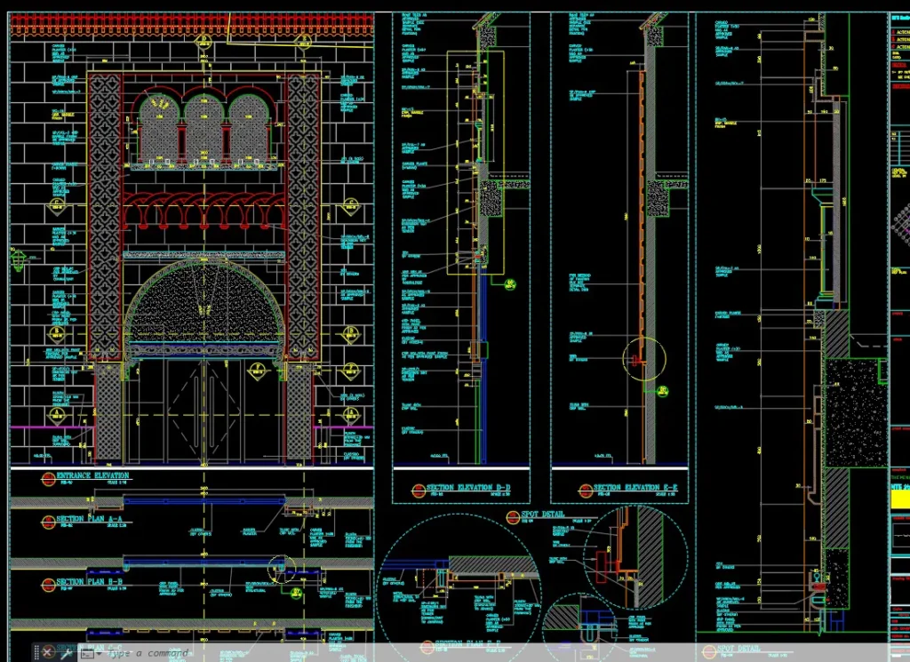
When an architect is drawing a section through a slab, he shows the thickness and materials. In some drawings, to reduce the load of preparation time, the architect writes refer to the structural drawing and its number. See Figure 3 sample of the global village development CAD drawings.
To sum up, preparing professional architectural drawings is not only about drafting. its design, planning, and daily work within an architectural firm. In addition, it lies in the process of architectural design process. The architect and senior present his professional skills and innovation in daily architectural work.